
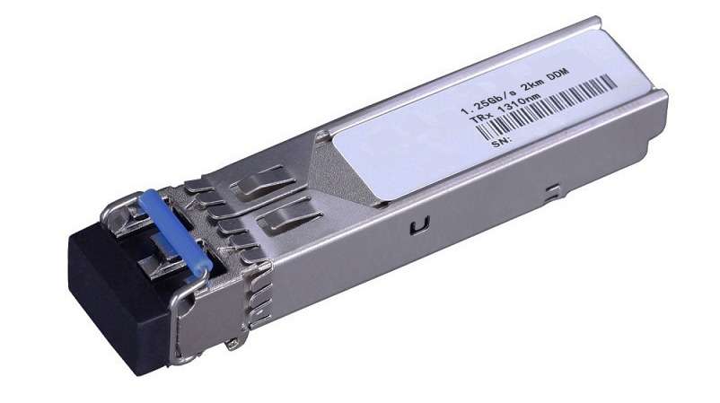
讯艾拓XAT-GM02-13 光模块Transceiver is a high performance, cost effective module which have a duplex LC optics interface. Standard AC coupled CML for high speed signal and LVTTL control and monitor signals. The receiver section uses a PIN receiver and the transmitter uses a1310 nm VCSEL laser, up to 9dB link budge ensure this module 1000Base Ethernet 550m application.
二、产品特点:² Up to 1.25Gb/s Data Links
² Hot-Pluggable
² Duplex LC connector
² Up to 2Km on 50/125μm MMF
² 1310nm VCSEL laser transmitter
² Single +3.3V Power Supply
² Monitoring Interface Compliant with SFF-8472
² Maximum Power <1W
² Industrial /Extended/ Commercial operating temperature range: -40°C to 85°C/-5°C to 85°C/-0°C to 70°C Version available
² RoHS compliant and Lead Free
Applications:
² Metro/Access Networks
² 1.25 Gb/s 1000Base-SX Ethernet
² 1×Fibre Channel
Other Optical Links
|
Parameter |
Symbol |
Min. |
Typical |
Max. |
Unit |
|
Storage Temperature |
TS |
-40 |
|
+85 |
°C |
|
Supply Voltage |
VCC |
-0.5 |
|
4 |
V |
|
Relative Humidity |
RH |
0 |
|
85 |
% |
|
Parameter |
Symbol |
Min. |
Typical |
Max. |
Unit |
|
|
Case operating Temperature |
Industrial |
TC |
-40 |
|
85 |
°C |
|
Extended |
-5 |
|
85 |
°C |
||
|
Commercial |
0 |
|
+70 |
°C |
||
|
Supply Voltage |
VCC |
3.135 |
|
3.465 |
V |
|
|
Supply Current |
Icc |
|
|
300 |
mA |
|
|
Inrush Current |
Isurge |
|
|
Icc+30 |
mA |
|
|
Maximum Power |
Pmax |
|
|
1 |
W |
|
|
Parameter |
Symbol |
Min. |
Typical |
Max. |
Unit |
Note |
|
Transmitter Section: |
|
|||||
|
Input differential impedance |
Rin |
90 |
100 |
110 |
W |
1 |
|
Single ended data input swing |
Vin PP |
250 |
|
1200 |
mVp-p |
|
|
Transmit Disable Voltage |
VD |
Vcc – 1.3 |
|
Vcc |
V |
2 |
|
Transmit Enable Voltage |
VEN |
Vee |
|
Vee+ 0.8 |
V |
|
|
Transmit Disable Assert Time |
Tdessert |
|
|
10 |
us |
|
|
Receiver Section: |
|
|||||
|
Single ended data output swing |
Vout,pp |
250 |
|
800 |
mv |
3 |
|
LOS Fault |
Vlosfault |
Vcc – 0.5 |
|
VCC_host |
V |
5 |
|
LOS Normal |
Vlos norm |
Vee |
|
Vee+0.5 |
V |
5 |
|
Power Supply Rejection |
PSR |
100 |
|
|
mVpp |
6 |
Note:
1. AC coupled.
2. Or open circuit.
3. Into 100 ohm differential termination.
4. 20 – 80 %
5. LOS is LVTTL. Logic 0 indicates normal operation; logic 1 indicates no signal detected.
6. All transceiver specifications are compliant with a power supply sinusoidal modulation of 20 Hz to 1.5MHz up to specified value applied through the power supply filtering network shown on page 23 of the Small Form-factor Pluggable (SFP) Transceiver Multi-Source Agreement (MSA), September 14, 2000.
|
Parameter |
Symbol |
Min. |
Typical |
Max. |
Unit |
Note |
|
Transmitter Section: |
||||||
|
Center Wavelength |
λc |
840 |
850 |
860 |
nm |
|
|
Spectral Width(RMS) |
σRMS |
|
|
0.85 |
nm |
|
|
Optical Output Power |
Pout |
-9 |
|
-3 |
dBm |
1 |
|
Extinction Ratio |
ER |
8.2 |
|
|
dB |
|
|
Optical Rise/Fall Time |
tr / tf |
|
|
260 |
ps |
2 |
|
Relative Intensity Noise |
RIN |
|
|
-120 |
dB/Hz |
|
|
Output Eye Mask |
Compliant with IEEE802.3 z (class 1 laser safety) |
|
||||
|
Receiver Section: |
|
|||||
|
Optical Input Wavelength |
λc |
770 |
|
860 |
nm |
|
|
Receiver Overload |
Pol |
0 |
|
|
dBm |
4 |
|
RX Sensitivity |
Sen |
|
|
-18 |
dBm |
4 |
|
RX_LOS Assert |
LOS A |
-29 |
|
|
dBm |
|
|
RX_LOS De-assert |
LOS D |
|
|
-19 |
dBm |
|
|
RX_LOS Hysteresis |
LOS H |
0.5 |
|
|
dB |
|
|
General Specifications: |
||||||
|
Data Rate |
BR |
|
1.25 |
|
Gb/s |
|
|
Bit Error Rate |
BER |
|
|
10-12 |
|
|
|
Max. Supported Link Length on 50/125μm MMF@1.25Gb/s |
LMAX |
|
550 |
|
m |
|
|
Total System Budget |
LB |
8 |
|
|
dB |
|
Note
1.The optical power is launched into MMF.
2.20-80%.
3.Jitter measurements taken using Agilent OMNIBERT 718 in accordance with GR-253.
4.Measured with PRBS 27-1 at 10-12 BER
Pin Assignment:
Diagram of Host Board Connector Block Pin Numbers and Name
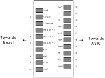
Diagram of Host Board Connector Block Pin Numbers and Names
Pin Function Definitions:
|
Pin No |
Name |
Function |
Plug Seq |
Notes |
|
1 |
VeeT |
Transmitter Ground |
1 |
1 |
|
2 |
TX Fault |
Transmitter Fault Indication |
3 |
|
|
3 |
TX Disable |
Transmitter Disable |
3 |
2 |
|
4 |
MOD-DEF2 |
Module Definition |
2 |
3 |
|
5 |
MOD-DEF1 |
Module Definition 1 |
3 |
3 |
|
6 |
MOD-DEF0 |
Module Definition 0 |
3 |
3 |
|
7 |
Rate Select |
Not Connected |
3 |
4 |
|
8 |
LOS |
Loss of Signal |
3 |
5 |
|
9 |
VeeR |
Receiver Ground |
1 |
1 |
|
10 |
VeeR |
Receiver Ground |
1 |
1 |
|
11 |
VeeR |
Receiver Ground |
|
1 |
|
12 |
RD- |
Inv. Received Data Out |
3 |
6 |
|
13 |
RD+ |
Received Data Out |
3 |
6 |
|
14 |
VeeR |
Receiver Ground |
3 |
1 |
|
15 |
VccR |
Receiver Power |
2 |
1 |
|
16 |
VccT |
Transmitter Power |
2 |
|
|
17 |
VeeT |
Transmitter Ground |
1 |
|
|
18 |
TD+ |
Transmit Data In |
3 |
6 |
|
19 |
TD- |
Inv. Transmit In |
3 |
6 |
|
20 |
VeeT |
Transmitter Ground |
1 |
|
Notes:
1. Circuit ground is internally isolated from chassis ground.
2. Laser output disabled on TDIS >2.0V or open, enabled on TDIS <0.8V.
3. Should be pulled up with 4.7k - 10 kohms on host board to a voltage between 2.0V and 3.6V. MOD_DEF(0) pulls line low to indicate module is plugged in.
4. Rate select is not used
5. LOS is open collector output. Should be pulled up with 4.7k – 10 kohms on host board to a voltage between 2.0V and 3.6V. Logic 0 indicates normal operation; logic 1 indicates loss of signal.
6.AC Coupled
SFP Module EEPROM Information and Management: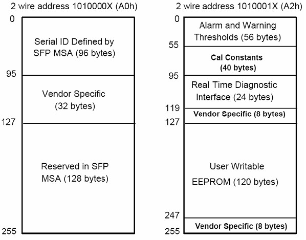
|
Data Address |
Length (Byte) |
Name of Length |
Description and Contents |
|
Base ID Fields |
|||
|
0 |
1 |
Identifier |
Type of Serial transceiver (03h=SFP) |
|
1 |
1 |
Reserved |
Extended identifier of type serial transceiver (04h) |
|
2 |
1 |
Connector |
Code of optical connector type (07=LC) |
|
3-10 |
8 |
Transceiver |
|
|
11 |
1 |
Encoding |
NRZ(03h) |
|
12 |
1 |
BR, Nominal |
Nominal baud rate, unit of 100Mbps |
|
13-14 |
2 |
Reserved |
(0000h) |
|
15 |
1 |
Length(9um) |
Link length supported for 9/125um fiber, units of 100m |
|
16 |
1 |
Length(50um) |
Link length supported for 50/125um fiber, units of 10m |
|
17 |
1 |
Length(62.5um) |
Link length supported for 62.5/125um fiber, units of 10m |
|
18 |
1 |
Length(Copper) |
Link length supported for copper, units of meters |
|
19 |
1 |
Reserved |
|
|
20-35 |
16 |
Vendor Name |
SFP vendor name: XAT |
|
36 |
1 |
Reserved |
|
|
37-39 |
3 |
Vendor OUI |
SFP transceiver vendor OUI ID |
|
40-55 |
16 |
Vendor PN |
Part Number: “XAT-GM02-13” (ASCII) |
|
56-59 |
4 |
Vendor rev |
Revision level for part number |
|
60-62 |
3 |
Reserved |
|
|
63 |
1 |
CCID |
Least significant byte of sum of data in address 0-62 |
|
Extended ID Fields |
|||
|
64-65 |
2 |
Option |
Indicates which optical SFP signals are implemented (001Ah = LOS, TX_FAULT, TX_DISABLE all supported) |
|
66 |
1 |
BR, max |
Upper bit rate margin, units of % |
|
67 |
1 |
BR, min |
Lower bit rate margin, units of % |
|
68-83 |
16 |
Vendor SN |
Serial number (ASCII) |
|
84-91 |
8 |
Date code |
XAT’s Manufacturing date code |
|
92-94 |
3 |
Reserved |
|
|
95 |
1 |
CCEX |
Check code for the extended ID Fields (addresses 64 to 94) |
|
Vendor Specific ID Fields |
|||
|
96-127 |
32 |
Readable |
XATspecific date, read only |
|
128-255 |
128 |
Reserved |
Reserved for SFF-8079 |
|
Data Address |
Parameter |
Accuracy |
Unit |
|
96-97 |
Transceiver Internal Temperature |
±3.0 |
°C |
|
100-101 |
Laser Bias Current |
±10 |
% |
|
100-101 |
Tx Output Power |
±3.0 |
dBm |
|
100-101 |
Rx Input Power |
±3.0 |
dBm |
|
100-101 |
VCC3 Internal Supply Voltage |
±3.0 |
% |
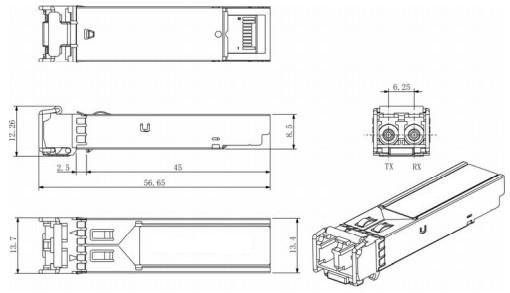
XAT-GM02-13
1.25Gb/s 2Km SFP Transceiver Hot Pluggable, Duplex LC, +3.3V, 1310nm, VCSEL, Multi-mode, DDM